Rhino

For 2.009 The Product Design Process, my team designed and built a rotary hammer attachment for use in a brick renovation process known as repointing.

Final Presentation v14.jpg

Repointing is the process of removing and replacing the mortar between bricks and is done on brick walls roughly every decade. The current method masons use to remove the mortar is grinding a seem through the mortar with an angle grinder and then chiseling it out by hand. The process is very slow, releases a lot of dust, and can damage the bricks by overcutting. Our solution was to use a percussive tool such as a rotary hammer for mortar removal because it is much faster and greatly reduces dust generation, as it does not pulverize the mortar but just knocks it out. However, our solution would not be complete without a way to stabilize the rotary hammer against the brick wall to insure proper control, cutting angle, and cutting depth. Thus Rhino was born.

Final Presentation v14.jpg

Our US patent pending tool attachment consists of an aluminum collar and a stainless steel guide. The guide is weldement made up of structural tube, runner, and guidance fin. The fin slides into the groove of the mortar joint as you cut to maintain a straight line. It also features a circular port which a vacuum can be attached to in case added dust mitigation is required.

Slide16.JPG

The guide can be easily removed and replace in case of damage, and it also comes in different sizes depending on cutting depth.

Slide17.JPG

The collar makes use of ball detents to snap the guide in place when it is inserted. It will also snap at right angles for easy adjustment. After adjustments are made, the handle can be lowered to secure it firmly. 

We brought our tool to real masons and they loved it. Our team has incorporated a company, Rhino Tools and Equipment Inc, and will continue to push our product into the market.

Wibbly Wobbly Yoyo

For 2.008 Design and Manufacture II, our team designed and manufactured 50 yoyos based on a time travel theme (a cross between The Doctor's Tardis and Harry's Time-Turner). Each yoyo half was comprised of 4 injection molded parts and 2 thermoformed parts. The yoyos featured a plastic hourglass filled with sand that would continue to spin on a ball bearing after the yoyo was caught.

Check out our project blog site for more details.

IMG_6627.jpg

Hemispherical Pinhole Camera

I was taking a photography class taught by acclaimed artist Lara Baladi. It was heavily focused on film photography and Lara encouraged experimentation. One of the topics we covered was the pinhole camera. It fascinated me because the pinhole camera is the most basic and pure form of photography. It does not require any lens, or focusing, or film, just a box with a hole in it and some light sensitive paper. I was also intrigued by the advantages the primitive technology gave. Everything in a pinhole camera's field of view is in focus without having a lens to focus it. What that means is that you can capture a picture that is beyond the limitations of modern lens technology. For instance, you can take wide angle shots without any edge distortion. I took this idea to the extreme and made my project to create a hemispherical pinhole camera that could take 180 degree field of view pictures. You could then display the spherical images and immerse yourself in the image like an analog VR.

The body of the hemispherical camera was made of paper mache because I could easily do a layup on a large balloon. I knew I wanted this camera to be big, to take big beautiful images, and the biggest balloon I could find was 3 ft in diameter so that determined the size. The paper mache gave a very durable body though it was pretty floppy. To fix that, I made a ring out of wood of slightly smaller inner diameter and pressed it around the edge and tapped it in place as a support (kinda ended up looking like Saturn). I then flipped it over and tapped the opening onto a large piece of black foam core with gaffers tape. The camera was spray painted black to prevent any light from passing through the thin walls.

2016-11-27 12.36.08.jpg
2016-11-27 17.15.43.jpg
2016-12-01 15.13.17.jpg

I created the pinhole in small piece of sheet metal which I tapped over an opening in the foam core. A small piece of tape acted as my shutter and I would just have to remove it to begin taking a picture. Since the aperture was so small, about 1 mm, and the focal length was so large, about 1.5 ft, the camera had an f-stop of almost f/500! That meant I needed very long exposure times, usually multiple hours depending on the light. A subject in direct sunlight took about 20 mins, while indoors was around 6 hours.

After some trial and error, I ended up with a couple pretty cool pictures. The first is a picture of the big dome at MIT as seen from Killian Court. Although much the grass and trees are underexposed, the building shows up really well and I kinda like the silhouette effect.

2016-12-06 17.24.39.jpg

The second picture is of the MIT Media Lab. The exposure on it took about an hour and what's great about long exposures is that you don't have to worry about pedestrians ruining your shot. The path outside the building was bustling with people but none of them stood still long enough to show up in the picture. Overall, I think the exposure is slightly better as you can see detail even in the ground, and I experimented with different ways of laying the photosensitive paper inside the camera.

2016-12-13 17.09.55.jpg

The goal of getting a full 180 degree image was not achieved but there is definitely promise in this technique. And the large images looked spectacular, especially in person.

Autonomous Swarming Buoy

buoy2.jpg

Over the summer of 2015, I worked in the Vortical Flow Research Lab at MIT with two grad students on creating autonomous swarming buoys to monitor dynamically changing ocean environments. These buoys can potentially collect any relevant data including temperature and chemical concentrations, though for the purposes of the research, we only tackled temperature measurement.

They also have the ability to communicate with each other and follow gradients in the data they're collecting.

buoy3.jpg

Above is the electronic setup I developed in about a week that allowed us to begin prototyping and testing the buoy's movement and effectiveness of the motor system as well as trying out some code. I put everything in a nice splash proof case I made out of acrylic and waterproof epoxy.

Motorized Electric Longboard

eboard2.jpg

I decided my longboard was collecting too much dust in my room and I should do something cool with it. I decided to motorize one of the back wheels. I order all the components I needed online from a hobbyist website and then began working on creating a motor mount.

eboard3.jpg

Getting the motor mount to fit onto the trucks was the most difficult part because of the irregular shape of the trucks. I ended up getting some air dry modeling clay and wrapped some around the trucks, pealed it off, traced it, then created a CAD form that, which I then put into a waterjet. The result was a pretty spectacular fit. You can see some of that process below.

eboard4.jpg

I went on to modify a case for it to house everything nicely so nothing will get damaged.

Door Knocker

I took a 3 day blacksmithing class at the MIT Merton C. Flemings Materials Processing Lab. I got to pick my own project so I decided to make classic-looking iron door knocker. But first I had to do a little bit of training so I made a practice piece. It includes the main techniques for basic forging such as drawing, punching, twisting, flat tapering, round tapering, and bending.

After that I moved on to making the door knocker. The base of it was made of a single flat bar of mild steel and the handle was made of square bar stock. It took about 4 hours over the course of two days and was quite a workout! In addition to the techniques I used on the practice piece I also split and dimpled it. Can you spot all the techniques?

File Aug 13, 5 36 08 PM.jpg

Mini Me

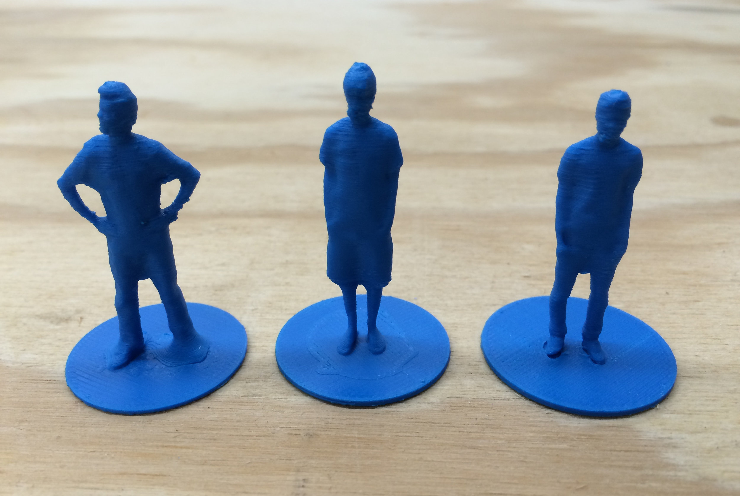
I was getting into 3D printing and wanted to create a mini figure of myself that I could use in board games. The first step was to generate a 3D model of my body. I found some free software online that could generate a model based on a set of photos taken of the object. I tried it out with something I had in my room, a rubik's cube.

2015-08-05 18.27.44.jpg

The result was pretty good though the surface was a bit lumpy. I thought the lumpiness wouldn't be that noticeable with an organic object like a human body so I decided to move forward with it.

I enlisted the help of a friend to take a series of full body photos of me. We did it on the stage of a lecture hall to get good even lighting and I made sure to set my camera to manual. I ended up with 50 photos in total, some full body and some close up on my face.

3D Body Scan Photos.jpg

I fed the photos into the software and ended up with a pretty good model. It had some trouble picking up the geometry of my hair and also one of my feet was a little wonky. I brought it over to Blender and did some retouching until I was happy with it. Then it was off to the printer.

2015-08-11 19.59.03.jpg
2015-08-11 20.26.04.jpg

The print came out great and didn't need any support material. Happy with the result, I repeated the process with two of my friends.

2015-08-11 22.19.27.jpg

Sundial

I wanted to learn how sundials work and figured the best way to do that is to try to make one myself. After extensive research on https://en.wikipedia.org/wiki/Sundial, among other sites, I felt I knew most of what I needed. However, I kept making adjustments as I discovered new factors I didn't account for.

The first thing I learned was that sundials are specific to a location because the sun's relation to time is different everywhere. The sundial I made was specific to MIT and would only work around there, so I put a small icon of the great dome on it to signify this.

I used some data online to layout the hour angles based on my location and thought I was pretty much set. Then I learned that you sometimes need to account for the width of the gnomon (the part of the sundial that casts the shadow). Because as the sun passes solar noon, the shadow goes from being cast from the left edge of the gnomon to the right edge and that will cause a jump in time if not accounted for. For a thin gnomon on a large base this effect is small and sometimes neglected, but I was making it out of half inch plywood on a one foot diameter base so I thought I should account for it.

sundial_base_pattern_12ft_corrected.png

The next interesting thing I learned was that sundials are designed for the average solar path, but the solar path changes throughout the year. The result is that a sundial can be off by up to around 20 minutes depending on your location. That was no good for me so I thought I should account for it. The difference between mean solar time and apparent solar time (measured by the sundail) is known as the equation of time. Data for this relation, which is also location specific, can be easily found online. I took the data, reversed it, and graphed it directly on the sundial to give an easy way to lookup what offset you have to apply to the sundial to arrive at actual time based on the month of the year. For example, if it's around the end of October, you look at the end of the 10th bar on the X axis and the graph reads +14, so you add 14 minutes to the time you read on the sundial.

sundial2.jpg
2015-07-13 19.53.17.jpg

Once the pattern was ready, I brought it over to a laser cutter and engraved it into some wood. Engraving went well but the laser wasn't strong enough to cut all the way through the wood so I brought it over to a waterjet to cut out the circular shape as well as the rectangular notches in the center that I used to insert the gnomon. The gnomon was also cut on the waterjet.

I assembled it then took it out in the morning to try it out. Looks like it was a little passed 8 at first glance but given the offset of -10 minutes in the middle of July, I would say it was 7:55.

2015-07-14 09.11.47.jpg

Simmons Hall T-Shirt Design

tshirt_editing.PNG

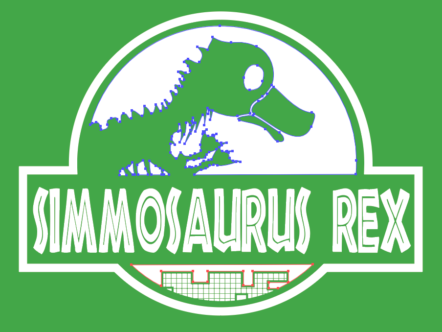
Simmons Hall was the dorm I lived in during my undergraduate time at MIT. At the start of every school year, the dorms and living groups have participate in a period called REX (Residence Exploration) where freshman can explore their different living options. Upperclassmen who volunteer, especially at Simmons, always go all out and hold lots of fun events for the incoming class. We also always get shirts. I designed the shirts for REX 2015 at Simmons. Based on Jurassic Park, the logo features a duck skeleton, as the rubber duck is our mascot. It also calls to attention our dorm's association with dinosaurs as we have had some terrible velociraptor infestations in the past (inside joke). The shirt came in different colors matching the color pallet of our dorm, as is tradition.

Simmosaurus REX.jpg